455 euro
КОД: BOX4V
Available
+380972782789
Отдел продаж
You can return new goods without any traces of use within 14 days of receiving them. Refund of the payment for the goods - within 14 days of receipt of the goods by the Seller. Transport costs shall be paid by the Buyer
Plastic parts are guaranteed for 10 years. Brass parts are guaranteed for 2 years, which is the usual warranty for couplings, taps, gate valves, flowmeters and other sanitary fittings
The 'BOX IN-4V' is wall-mounted manifold box with ball valves is designed to control the flow of brine in 4 geothermal loops.
The ball valves help to fill with brine and remove air from the geothermal circuits, as well as to shut off the geothermal circuits if necessary.
With a 13 mm spanner it is easy to turn the stem of the installed ball valves, adjust or shut off the flow of brine in the geothermal loops.
Connection 'BOX IN-4V' to the geothermal heat pump is possible on either the right or left hand side of the heat pump. Two stainless steel doors on opposite sides of the manifold 'BOX' are provided for access to the valves.
Hydraulic connections:
- on the top, 3 detachable brass unions with 3/4'' female thread for the installation of filling taps, air vent valves, level vessel, pressure gauge, safety group, etc;
- on the side, 2 detachable brass unions with 1'' male thread for connecting a geothermal heat pump;
- at the bottom 8 polyethylene pipes Ø40 mm for geothermal loops.
The most compact and installation-friendly manifolds boxes on the market!
Geothermal box enclosure dimensions 'BOX IN-4V': length 408 mm, width (depth) 164 mm, height 400 mm. Overall dimensions with connectors and threads: length 473 mm, width (depth) 164 mm, height 517 mm.
Working pressure of up to 5 atmospheres of brine. Short-term overpressure up to 10 atmospheres possible.
Brine operating temperatures: minus 15 °C to +50 °C.
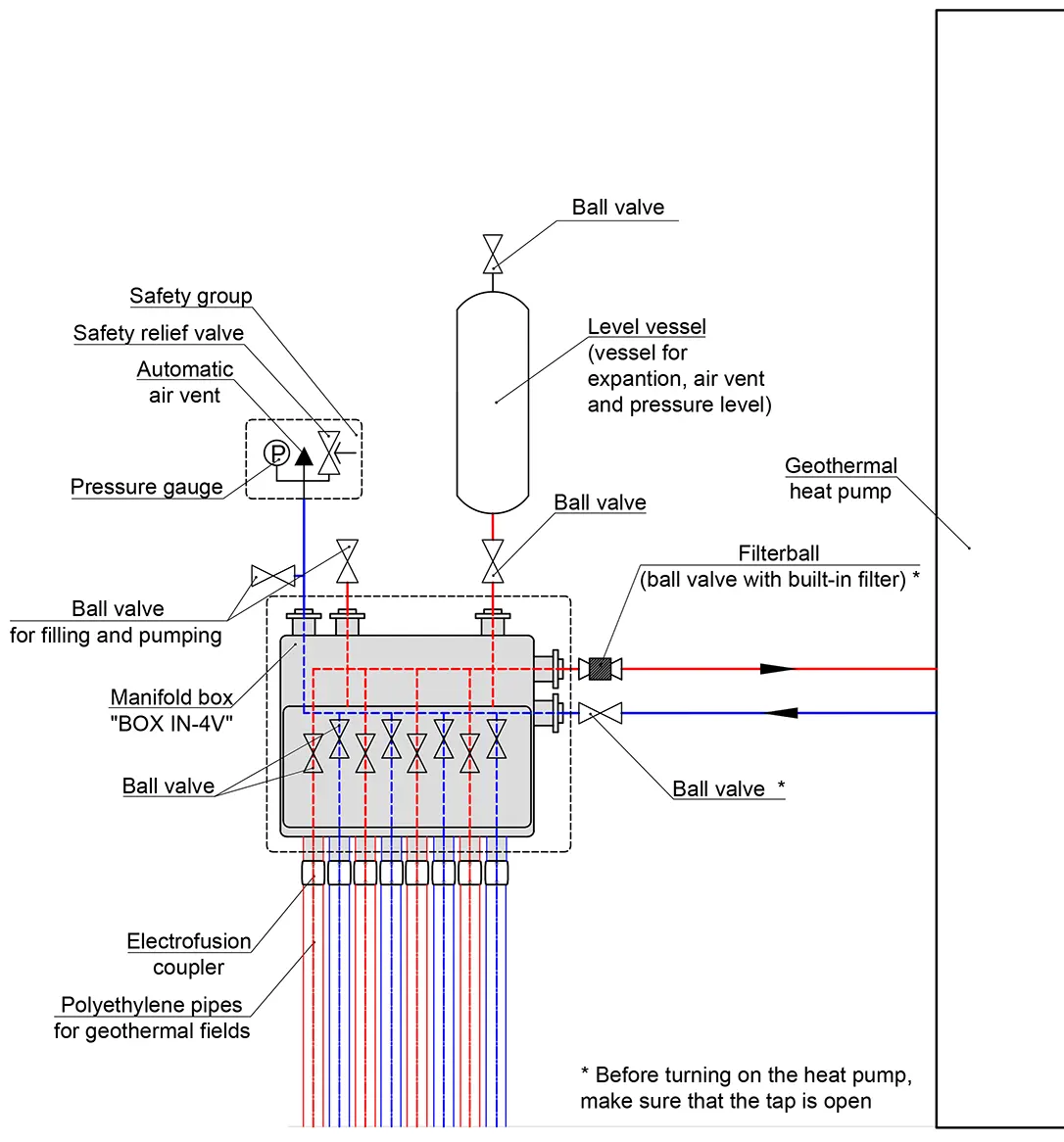
We recommend two typical hydraulic schemes for connecting a heat pump to a `BOX` geothermal manifold:
Scheme 1 is the most compact, fastest and cheapest to install. A possible limitation to the use of circuit 1 is that the size or capacity of the existing level vessels is inadequate.
Advice for using Scheme 1 when carrying out work on filling the geothermal system with brine:
- Close the ball valves installed between the manifold box and the geothermal heat pump
- When filling the system, in case the brine pressure exceeds the set pressure of the safety valve for a short time, close the upper plastic cap on the safety valve for a temporary blocking of the valve
- Important: after having filled the collectors - unblock the safety valve
- Open the ball valves installed between the `BOX` manifold box and the heat pump
Recommended hydraulic connection diagram No. 1 for the geothermal manifold box 'BOX IN-4V':

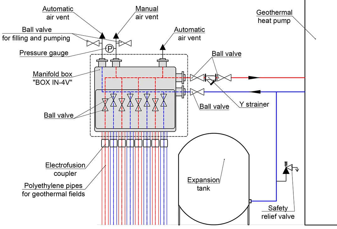
Scheme 2 prevents exceeding the maximum allowable pressure brine in the heat pump. This is a relatively common mistake made by inexperienced installers that can damage the geothermal heat pump. We recommend Scheme 2 if the heat pump is to be installed, commissioned or maintained by beginners.
Recommended hydraulic connection scheme 2 for the geothermal manifold box 'BOX IN-4V':
Example of installation of geothermal pipes in plasterboard, for further decoration with tiles or painting:

